Electromagnetic induction, a fundamental principle governing inductance in a circuit, finds practical application in devices like the Tesla coil. The behavior of inductance in a circuit is accurately modeled and analyzed using software such as SPICE (Simulation Program with Integrated Circuit Emphasis). Moreover, the Institute of Electrical and Electronics Engineers (IEEE) provides comprehensive standards and guidelines regarding inductance in a circuit design and safety. Oliver Heaviside, a prominent electrical engineer, significantly contributed to understanding and mathematically formalizing the concepts underpinning inductance in a circuit, thus, offering better methods to evaluate related scenarios. Understanding inductance in a circuit is crucial for preventing unexpected voltage spikes and optimizing circuit performance in various applications.
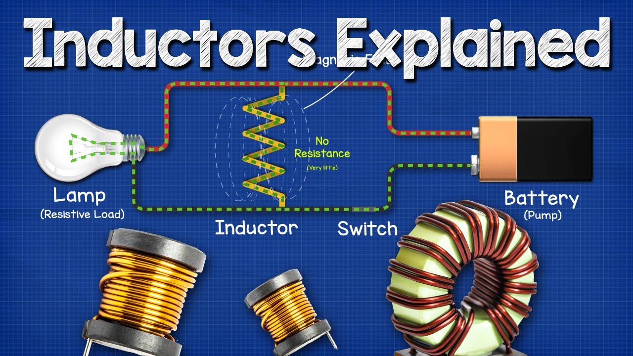
Image taken from the YouTube channel The Engineering Mindset , from the video titled Inductors Explained – The basics how inductors work working principle .
Imagine a scenario: you switch off a seemingly simple circuit, perhaps controlling a motor or a relay. Instead of a quiet shutdown, a surprising and potentially damaging voltage spike erupts. This is often the unseen hand of inductance at play, a fundamental property of electrical circuits that can manifest in unexpected ways.
Inductance is more than just a theoretical concept; it’s a critical factor influencing the behavior of countless electronic devices.
Its importance is sometimes overlooked, leading to design flaws, performance limitations, or even catastrophic failures. Understanding inductance is paramount for anyone working with electrical engineering.
Demystifying Inductance
So, what exactly is inductance? In essence, inductance is the property of an electrical circuit to oppose changes in current flow. This opposition arises from the circuit’s ability to generate a magnetic field when current flows through it.
This seemingly simple definition masks a wealth of complex electromagnetic phenomena, governing everything from the operation of transformers to the behavior of high-frequency circuits.
Inductance in Electrical Circuits
Inductance plays a crucial role in various electrical circuits, both large and small.
It is present in motors, generators, power supplies, and signal processing circuits. Its effects are usually more pronounced at higher frequencies or when dealing with rapidly changing currents.
Thesis Statement: A Journey into the World of Inductance
This article embarks on a journey to demystify inductance, providing a comprehensive exploration of its fundamental principles, practical applications, and potential pitfalls.
We will delve into the physics behind inductance, examine the properties of inductive components, and analyze the behavior of circuits containing inductors.
Our aim is to empower you with the knowledge and understanding necessary to effectively harness the power of inductance in your own electrical engineering endeavors.
Imagine a scenario: you switch off a seemingly simple circuit, perhaps controlling a motor or a relay. Instead of a quiet shutdown, a surprising and potentially damaging voltage spike erupts. This is often the unseen hand of inductance at play, a fundamental property of electrical circuits that can manifest in unexpected ways.
Inductance is more than just a theoretical concept; it’s a critical factor influencing the behavior of countless electronic devices. Its importance is sometimes overlooked, leading to design flaws, performance limitations, or even catastrophic failures. Understanding inductance is paramount for anyone working with electrical engineering.
So, what exactly is inductance? In essence, inductance is the property of an electrical circuit to oppose changes in current flow. This opposition arises from the circuit’s ability to generate a magnetic field when current flows through it.
This seemingly simple definition masks a wealth of complex electromagnetic phenomena, governing everything from the operation of transformers to the behavior of high-frequency circuits. Inductance plays a crucial role in various electrical circuits, both large and small.
It is present in motors, generators, power supplies, and signal processing circuits. Its effects are usually more pronounced at higher frequencies or when dealing with rapidly changing currents.
This article embarks on a journey to demystify inductance, providing a comprehensive exploration of its fundamental principles, practical applications, and potential pitfalls. Now, before we delve into the practical implications and applications of inductance, it’s essential to understand the underlying physics that governs this phenomenon.
The Physics Behind Inductance: A Deep Dive into Electromagnetism
Inductance isn’t just an abstract electrical property. It’s deeply rooted in the fundamental laws of electromagnetism. Understanding the physics behind inductance provides a solid foundation for comprehending its behavior in various circuits and applications.
Magnetic Fields and Current Flow
The cornerstone of inductance lies in the intimate relationship between magnetic fields and electric current. Whenever an electric current flows through a conductor, it generates a magnetic field around it.
The strength of this magnetic field is directly proportional to the magnitude of the current. This phenomenon is not merely a correlation; it’s a fundamental law of nature.
Consider a straight wire carrying a current. The magnetic field lines form concentric circles around the wire, with the field strength diminishing as you move further away.
For a coil of wire, the magnetic fields from each turn add up, creating a stronger, more concentrated magnetic field within the coil. This is the basic principle behind inductors.
Faraday’s Law of Induction
Faraday’s Law of Induction is the key to understanding how inductance opposes changes in current. This law states that a changing magnetic flux through a circuit induces an electromotive force (EMF), which is a voltage.
Induced EMF (Voltage)
When the magnetic flux linking a circuit changes – for instance, due to a changing current – a voltage is induced in the circuit. This induced voltage is proportional to the rate of change of the magnetic flux.
The faster the magnetic flux changes, the greater the induced voltage. This is why inductance is most noticeable when dealing with rapidly changing currents, such as in AC circuits or during switching events.
Mathematical Representation of Faraday’s Law
Mathematically, Faraday’s Law is expressed as:
ε = -N (dΦ/dt)
Where:
- ε is the induced EMF (voltage).
- N is the number of turns in the coil.
- Φ is the magnetic flux.
- dΦ/dt is the rate of change of magnetic flux with respect to time.
The negative sign in the equation signifies Lenz’s Law, which we’ll discuss shortly. This equation is critical for calculating the induced voltage in a circuit due to a changing magnetic field.
Lenz’s Law: Opposition to Change
Lenz’s Law is a direct consequence of the principle of energy conservation. It dictates that the induced EMF always opposes the change in current that caused it.
This opposition is crucial for understanding how inductance resists changes in current flow. If the current is increasing, the induced EMF will act to reduce the current. Conversely, if the current is decreasing, the induced EMF will act to increase the current.
This opposition is not an arbitrary phenomenon; it’s a fundamental requirement to prevent the violation of energy conservation.
If the induced EMF aided the change in current, the current would increase indefinitely, creating energy out of nothing, which is impossible.
The Henry (H): The SI Unit of Inductance
The Henry (H) is the standard unit of inductance in the International System of Units (SI). One Henry is defined as the inductance of a circuit in which a current changing at a rate of one ampere per second results in an induced EMF of one volt.
Practical Examples of Inductance Values
The inductance values of different components vary widely depending on their design and materials. Here are a few examples:
- A small air-core inductor used in a radio circuit might have an inductance of a few microhenries (µH).
- A larger iron-core inductor used in a power supply might have an inductance of several millihenries (mH).
- A transformer, which relies on mutual inductance between coils, can have inductance values ranging from millihenries to several Henries.
Understanding the Henry and typical inductance values helps engineers select appropriate components for specific applications. Furthermore, it provides a tangible scale for grasping the magnitude of inductance in different circuits.
The discussion of inductance wouldn’t be complete without a closer look at the physical components that embody this property. These components, known as inductors, are specifically designed to introduce a controlled amount of inductance into a circuit. They form the bridge between the theoretical understanding of electromagnetism and the practical world of electronic design.
Inductors: Physical Manifestations of Inductance
Inductors, also frequently called coils or chokes, are fundamental components in electrical engineering, intentionally designed to exhibit inductance. Unlike resistors or capacitors which primarily offer resistance or capacitance respectively, inductors are designed around the principles of electromagnetic induction. Their primary purpose is to store energy in a magnetic field when current flows through them. This makes them essential components in a wide range of applications.
Types of Inductors and Their Applications
Inductors come in various forms, each with its own characteristics and suited for specific applications. The core material and physical construction significantly influence an inductor’s performance.
-
Air-Core Inductors:
As the name suggests, air-core inductors utilize air as their core material. They are typically used in high-frequency applications where core losses need to be minimized.
These inductors are characterized by lower inductance values compared to those with ferromagnetic cores. This makes them suitable for radio frequency (RF) circuits and applications where precision is crucial. -
Iron-Core Inductors:
Iron-core inductors employ a core made of iron or iron alloys. The high permeability of iron allows for significantly higher inductance values compared to air-core inductors with the same number of turns.
They are commonly used in power supplies and audio circuits.
Iron-core inductors are generally less expensive, but can suffer from core losses and saturation effects at high frequencies. -
Ferrite-Core Inductors:
Ferrite-core inductors use ferrite, a ceramic material composed of iron oxide combined with other metal oxides. Ferrite cores offer a good balance between high permeability and low core losses, making them suitable for a wide range of frequencies.
They are frequently found in switch-mode power supplies, EMI filters, and high-frequency circuits. -
Toroidal Inductors:
Toroidal inductors are characterized by their donut shape, which concentrates the magnetic field within the core. This construction minimizes electromagnetic interference (EMI) and provides high inductance values.
Toroidal inductors are often used in applications where low EMI is critical, such as audio equipment and sensitive electronic devices.
The Solenoid: A Common Inductor Configuration
The solenoid represents a fundamental and widely used type of inductor. It consists of a coil of wire wound into a tightly packed helix.
When current flows through the wire, a relatively uniform magnetic field is created inside the solenoid.
Solenoids find applications in various electromechanical devices. Some examples include relays, actuators, and valves.
In these applications, the magnetic field generated by the solenoid is used to exert a force, thereby causing mechanical movement.
Factors Affecting Inductance
The inductance value of an inductor is determined by several factors, including:
-
Number of Turns (N): Inductance is proportional to the square of the number of turns in the coil (L ∝ N²). Increasing the number of turns significantly increases the inductance.
-
Core Material (μ): The permeability of the core material greatly affects inductance. Higher permeability materials (like iron or ferrite) result in higher inductance values.
-
Geometry (Shape and Size): The physical dimensions of the inductor, such as the coil’s length, diameter, and cross-sectional area, influence inductance. Tighter and more compact geometries generally lead to higher inductance.
- For example, a shorter, wider coil will have a higher inductance than a long, thin coil, assuming all other parameters are constant.
-
Spacing between turns: Closer spacing between turns increases inductance by concentrating the magnetic field.
Understanding these factors is crucial for selecting or designing inductors with the appropriate inductance value for a specific application. Carefully considering these parameters allows engineers to optimize circuit performance and achieve desired results.
Iron cores enable higher inductance values, but their presence significantly alters circuit behavior. Understanding how these altered behaviors show up in DC and AC circuits is essential for any electrical engineer or hobbyist. Let’s explore this and how these properties are used in common circuits.
Inductance in Action: Circuit Analysis and Behavior
Inductance, while fascinating as a standalone concept, truly comes to life when integrated into electrical circuits. Its behavior, especially within both Direct Current (DC) and Alternating Current (AC) environments, is critical to understand for effective circuit design. Here, we’ll analyze these effects, introducing essential concepts such as reactance, impedance, and time constants.
DC Circuits: The Initial Surge and Gradual Stabilization
In a DC circuit, an inductor presents a unique transient behavior. When a DC voltage source is initially connected to an inductor, the current doesn’t instantaneously jump to its maximum value. Instead, it increases gradually, creating a current ramp-up.
This gradual increase is due to the inductor’s opposition to changes in current, as dictated by Lenz’s Law. During this period, the inductor stores energy in its magnetic field. Once the current reaches a steady state, the inductor behaves like a short circuit (assuming it has negligible DC resistance).
The Time Constant (L/R): Gauging the Transient Response
The time constant, denoted as τ (tau) and calculated as L/R (Inductance / Resistance), is a crucial parameter in analyzing the transient response of an inductive DC circuit. It represents the time it takes for the current to reach approximately 63.2% of its maximum value.
After five time constants (5τ), the current is generally considered to have reached its steady-state value. This time constant dictates the speed at which the inductor charges and discharges, and is vital for design considerations in timing and switching circuits.
AC Circuits: Reactance, Impedance, and Phase Shifts
When an inductor is placed in an AC circuit, its behavior becomes significantly different from its DC counterpart. In AC circuits, the continuously changing current results in a continuously changing magnetic field, which in turn induces a back EMF that opposes the current flow.
This opposition to AC current flow, offered by an inductor, is called reactance.
Inductive Reactance (XL): Quantifying Opposition in AC
Reactance (XL) is measured in ohms and is directly proportional to the frequency (f) of the AC signal and the inductance (L):
XL = 2πfL
This equation reveals that higher frequencies and larger inductance values result in greater opposition to the AC current. The reactance is what determines how much current will flow at a given voltage and frequency.
Voltage and Current: A Phase Relationship
In a purely inductive AC circuit, the voltage across the inductor leads the current through it by 90 degrees. This phase shift is a fundamental characteristic of inductors in AC circuits. When voltage is at its maximum, the current is zero, and vice versa.
This relationship has profound implications for power calculations and circuit design.
Impedance (Z): The Total Opposition to AC Current
In real-world AC circuits, inductors are almost always combined with resistors and sometimes capacitors. Impedance (Z) is the total opposition to current flow in such AC circuits.
It is a combination of resistance (R) and reactance (XL), and is also measured in ohms. The impedance of an RL circuit is calculated as:
Z = √(R² + XL²)
Impedance determines the magnitude of the current flowing in an AC circuit, considering both resistive and reactive components.
RL Circuits: A Blend of Resistance and Inductance
RL circuits, comprising resistors and inductors, are fundamental building blocks in many electronic systems.
Their behavior combines the characteristics of both components.
Transient and Steady-State Analysis
In an RL circuit connected to a DC source, the current rises exponentially, as described by the time constant (L/R). In the steady state, the inductor acts as a short circuit, and the current is limited only by the resistor. With an AC source, the current is determined by the impedance of the circuit.
Applications of RL Circuits
RL circuits find use in a variety of applications:
- Filtering: RL circuits can act as simple low-pass filters, attenuating high-frequency signals.
- Timing Circuits: The time constant of an RL circuit can be used to create timing delays in various applications.
- Snubber Circuits: Used to suppress voltage spikes when switching inductive loads.
RLC Circuits: Resonance and Complex Behavior
RLC circuits, containing resistors, inductors, and capacitors, exhibit even more complex behavior due to the interaction between inductance and capacitance. RLC circuits, while more complex, are foundational to many modern electronics.
Resonance: A Key Phenomenon
One of the most important characteristics of RLC circuits is resonance. At the resonant frequency, the inductive reactance (XL) and capacitive reactance (XC) cancel each other out, resulting in minimum impedance and maximum current flow.
The resonant frequency (f₀) is given by:
f₀ = 1 / (2π√(LC))
RLC circuits are used extensively in:
- Radio Receivers: Tuning circuits to select specific frequencies.
- Oscillators: Generating periodic signals.
- Filters: Creating highly selective frequency responses.
Inductance in circuits has revealed some of its characteristics. Now it is important to discuss the practical consequences of inductance, including voltage spikes, electromagnetic interference (EMI), and energy storage. Highlighting the potential dangers and benefits associated with inductance in real-world applications is critical for anyone designing with inductive components. We will also touch on the historical context, acknowledging the scientists who paved the way for our understanding.
The "Shocking Truth" and Practical Implications: Voltage Spikes, EMI, and Energy Storage
Inductance, while a fundamental property in electrical circuits, can manifest in ways that are both beneficial and potentially harmful. Voltage spikes, electromagnetic interference (EMI), and energy storage are three key areas where the practical implications of inductance become evident. Understanding these implications is essential for designing robust and reliable electronic systems.
The Peril of Voltage Spikes
One of the most concerning consequences of inductance is the generation of voltage spikes. These spikes occur when the current through an inductor changes rapidly, such as when a circuit is switched off or when a switching device is used.
According to Faraday’s Law, a rapidly changing current induces a large voltage across the inductor. This voltage can far exceed the normal operating voltage of the circuit.
The induced voltage spike can damage sensitive components like transistors, integrated circuits, and diodes. Protecting circuits from these voltage spikes is crucial for ensuring reliability.
Common protection methods include using flyback diodes (also known as snubber diodes) across inductive loads to dissipate the energy stored in the inductor during switching. Transient voltage suppressors (TVS diodes) can also be used to clamp the voltage to a safe level.
Electromagnetic Interference (EMI): An Unwanted Radiated Effect
Inductors, by their very nature, generate magnetic fields. While these fields are essential for their intended function, they can also cause electromagnetic interference (EMI).
EMI occurs when the magnetic fields generated by an inductor radiate into the surrounding environment. This radiation can interfere with the operation of other electronic devices nearby.
Switching power supplies, motor drives, and other circuits with rapidly changing currents are particularly prone to generating EMI. Mitigating EMI is crucial for ensuring electromagnetic compatibility (EMC) of electronic devices.
Strategies for reducing EMI from inductors include:
- Shielding: Enclosing the inductor in a conductive shield can contain the magnetic fields and prevent them from radiating.
- Toroidal inductors: These inductors have a core shape that minimizes external magnetic fields.
- Filtering: Using filters to block high-frequency noise generated by the inductor.
Energy Storage: Harnessing the Magnetic Field
Inductors have the ability to store energy in their magnetic fields. This property makes them useful in a variety of applications, such as:
- Switching power supplies: Inductors are used to store energy and transfer it to the output.
- DC-DC converters: Inductors are used to regulate voltage levels.
- Energy harvesting circuits: Inductors can store energy harvested from the environment.
The energy stored in an inductor is proportional to the inductance (L) and the square of the current (I) flowing through it (E = 1/2 L I^2). This stored energy can be released back into the circuit when needed.
Acknowledging the Pioneers: Faraday and Henry
The understanding of inductance and electromagnetic induction owes its foundation to the groundbreaking work of Michael Faraday and Joseph Henry. In the 1830s, both scientists independently discovered the principle of electromagnetic induction, which states that a changing magnetic field induces a voltage in a nearby conductor.
Faraday’s Law of Induction provides the mathematical relationship between the induced voltage, the number of turns in the coil, and the rate of change of magnetic flux. Henry’s work focused on self-induction, where a changing current in a coil induces a voltage in the same coil. Their discoveries laid the foundation for the development of electric generators, transformers, and many other electromagnetic devices.
Transformers: Harnessing Mutual Inductance
Transformers are a quintessential application of mutual inductance. They consist of two or more coils wound around a common core. When an alternating current flows through one coil (the primary winding), it creates a changing magnetic field that induces a voltage in the other coil(s) (the secondary winding(s)).
The ratio of the number of turns in the primary and secondary windings determines the voltage transformation ratio. Transformers are used to step up or step down voltage levels.
Transformers are essential components in power transmission and distribution systems, allowing efficient transmission of electrical energy over long distances. They are also widely used in electronic devices to provide the required voltage levels for different circuits.
FAQs: Inductance in a Circuit
Here are some frequently asked questions about inductance in circuits to help clarify this important concept.
What exactly is inductance?
Inductance is a circuit element’s property to oppose changes in current. It’s caused by the magnetic field created around a conductor carrying current. Inductance is measured in Henries (H).
How does inductance affect a circuit?
Inductance introduces opposition to changes in current flow. When the current through an inductor changes, it induces a voltage that opposes this change. This opposition can smooth out current fluctuations in a circuit.
Why is inductance sometimes called "electrical inertia"?
The term "electrical inertia" is often used because inductance resists changes in current, similar to how inertia resists changes in motion. It takes time and energy to build up or collapse the magnetic field associated with inductance in a circuit.
What are some practical applications of inductance in a circuit?
Inductors are used in various applications, including filters, transformers, and energy storage devices. In power supplies, they smooth out voltage and current. They also play a crucial role in tuning circuits for radio communication.
So, that’s the lowdown on inductance in a circuit! Hopefully, you’ve got a better grip on how it all works. Now go forth and build some awesome circuits… just be careful out there!